Connectivity & Glitch Verification Acceleration for VLSI Designs Using Static Methodology
Case Study by Arun Selvaraju & Abhishek Ghate of HCLTech
Case Study Overview
HCLTech discusses their robust methodology for early checking of connection integrity at the RTL and netlist level for both the block and the top-level.
HCL used this methodology to successfully verify connectivity and glitches on an active SoC design using Real Intent’s SafeConnect in a few days. This is in contrast to several weeks work required with alternative methods.
I. Efficient Connectivity Checking Needed for Structured Designs
Design teams are managing increasing SoC complexity through chip architectures that structurally connect various functional components.
HCLTech thoroughly verifies these interconnected blocks and sought to improve the efficiency of our methodology for verifying the connections between the pre-verified components, especially given that the number of connections can reach millions.
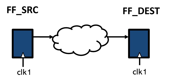
Connectivity Checking
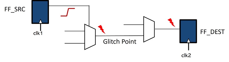
Glitch error
Robust connectivity rules can identify and remedy issues early, for example:
- Eliminating block abutment issues that can show up during physical design
- Identifying specific instance port clock domains
- Detecting driven pins within a module
- Ensuring glitch-free input pins for specified instances.
Defining these connectivity rules requires checking signal connectivity across multiple blocks and hierarchical levels and covering items such as the existence of the connection and its passage through specific modules. The paths may include state elements, flops, clock gating, power logic, and other components.
Later in this case study, we will discuss in depth several rules HCL defined at both the block and top levels for one of our complex SoCs, which had six interconnected subsystems. We analyzed the results for each of the defined rules using the generated report files and the integrated debug GUI.
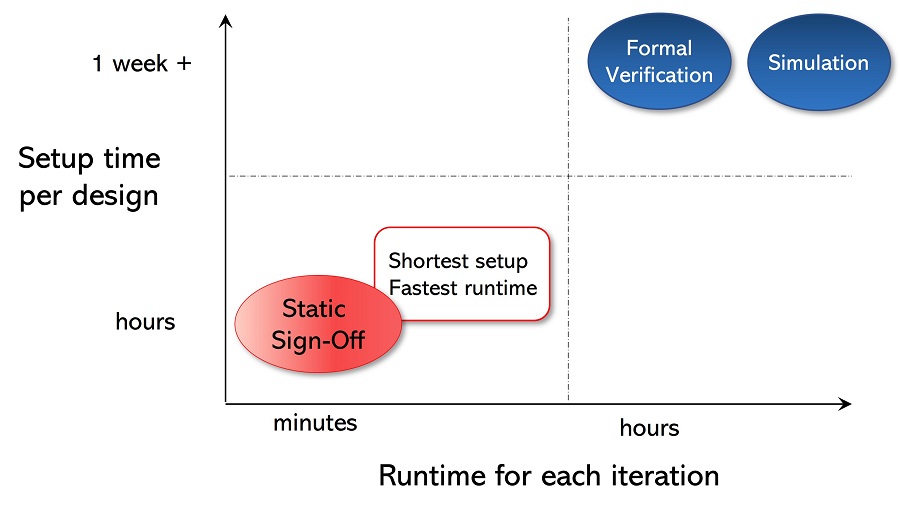
II. Formal, Simulation, & STA Limitations for Connectivity & Glitch Checking
For this application, formal, simulation, and script-based connectivity checking options present challenges with scalability, debugging, and efficiency, and can lead to problems being identified late in the design flow.
II-1. Formal verification limitations
HCL had previously done its connectivity checking and glitch detection exclusively using formal technology. Formal methods use abstract mathematical models, logic, and formal languages to analyze the behavior of systems.
This abstraction level can raise challenges in debugging and resolving issues within the design, and computational complexities can lead to longer analysis times and potential scalability issues.
II-2. Simulation limitations
Using simulation to verify connectivity also poses challenges such as limited coverage. This is because simulations utilize manually created test benches and tests which might not cover all possible scenarios and corner cases.
Further, developing and running comprehensive tests is both time-consuming and engineering time intensive.
Connectivity & glitch checking setup & runtime information can be found in Section V.
II-3. Static timing analysis limitations
False paths are timing paths in a design that are explicitly declared to not require timing analysis; the paths are deemed non-critical or additional design considerations justify excluding them from timing checks.
Because static timing analysis (STA) tools do not analyze false paths during the timing analysis process, the STA tools will not detect any glitches or timing violations that may occur on them.
Additionally, script-based connectivity checking options have capacity/speed limits. and may not identify connectivity issues until late in the design flow, where it is more expensive to remedy them. Further, the scripts require ongoing maintenance.
III. HCL’s Basis for Deploying Real Intent SafeConnect for Connectivity & Glitch Checking
HCL deployed a static sign-off methodology for our connectivity and glitch checking to overcome the limitations described in section II above. We perform connectivity checking at every stage of the design flow, with register transfer language (RTL) design completeness increasing with each stage.
HCL adopted Real Intent SafeConnect to achieve our early RTL and gate-level netlist sign-off for both IP blocks and SoCs, due to the following tool advantages that we found:
Fast, efficient rule definition, different rules at subsequent design stages
The rule definition process is easy and convenient – no testbenches or assertions are required. We can develop our own rules for our company, a specific project, or an individual.
Slightly different rules may be needed to analyze each version; SafeConnect lets us define our checks easily, identifying which RTL version the tool should analyze.
Its flexible command options reduce noise in reporting, and help us avoid waivers.
High Capacity & Performance
SafeConnect reads our RTL design, constraints, power intent (UPF), performs analysis, and generates comprehensive violations report based on HCL’s specific rules.
SafeConnect’s connectivity and glitch checking is significantly faster, with higher capacity compared with methods using formal, simulation or using TCL-based scripts. We have benchmark details for this below in section V.
Customized Connectivity Debug
Real Intent’s integrated iDebug feature enables us to view schematics of the targeted problematic connections, along with their locations in the RTL.
This makes HCL’s debug process easier, and we can more efficiently iterate through the design flow to quickly achieve successful sign-off.
Low Setup & Maintenance
This static methodology requires minimal support and eliminates the need for ongoing maintenance efforts; e.g., we were not required to create assertions or build test benches during setup, unlike traditional formal and simulation methods.
We efficiently defined and configured design rules. Also, no complex TCL scripts were required to manually implement the checks and no need for ongoing maintenance.
IV. Proposed Static Sign-Off Methodology
The steps for our methodology were as follows:
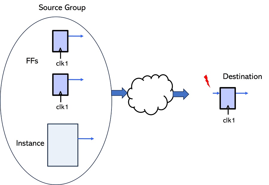
Step 1 – Define the sources & destinations to specify paths
The source or destination can be a single signal or collection of signals, such as pin, port, and nets.
SafeConnect has multiple grouping commands for us to select specific module/instance pins, flip-flops in the full chip, specific modules, and instances with switches for exclusion to reduce noise and group only the required signal set.
Step 2 – Define connectivity & glitch checks
There can be multiple scenarios for connectivity testing and glitch detection. Examples are:
- Connection present has combinational logic
- Connection passes through the specified modules
- Connections are present in the same power domain
- Connection is driven or not
- Specified path has potential glitches
- Glitch reaches the specified signal group
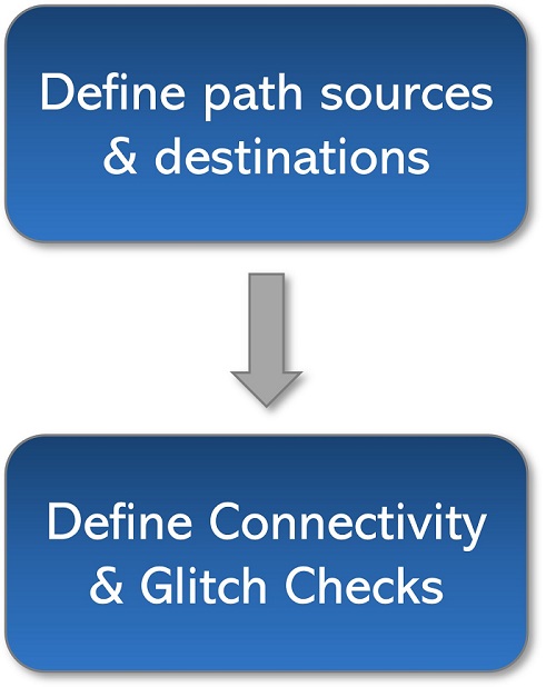
Two-step setup
V: Results: Reduced Setup & Runtimes
| Design | Design Size: equiv NAND2 gates | # of connectivity & glitch rules | Runtime |
| 1 | 20,000,000 | 8 | 04 mins 29 secs |
| 2 | 10,000,000 | 12 | 02 mins 10 secs |
| 3 | 370,000 | 7 | 01 mins 08 secs |
SafeConnect’s runtime was only a few minutes vs. hours for HCL’s formal verification flow for the same purpose
The SoC design used for this methodology study includes an ARM-based CPU sub-system and artificial intelligence (AI) IP instantiation to support AI capabilities. The SoC also has a GIC interrupt controller, a debug subsystem, a watchdog timer, a peripheral subsystem that offers connectivity to external devices, a RAM/ROM subsystem to manage memory operations, and DMA controllers to facilitate intra-system data transfers, and more.
Setting up SafeConnect and defining our connectivity rules took us less than 8 hours — we had the flow up and running the same day. We used some of the rules for other sub-systems, which helped reduce our setup time for them.
This is in contrast with methodologies deploying formal or simulation which require technical expertise –setting up those environments takes more than a week of effort and the effort increases with complexity of the block being tested.
VI: Results: Bugs Found & Reports
We successfully verified the connectivity and addressed glitches in the design with this static sign-off methodology.
Below are examples of what the tool reported for selected rules that we defined, including bugs found.
HCL RULE 1
The specified signal group must drive design logic.
Report: All the signals in the group that did not drive any logic were reported, along with their location, under the FAIL header
HCL RULE 2
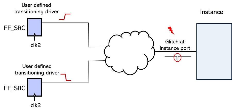
No glitch should reach the input pins of any instance in the design.
Report: All input pins for which the drivers converged to cause a glitch in the design were reported, along with the instance name.
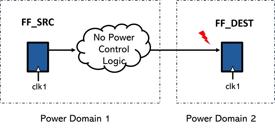
HCL RULE 3
Connectivity from source to destination must be in the same power domain.
Report: All paths containing isolation cells or level shifters were filtered out. All path where the source and destination were in different domains were reported.
HCL RULE 4
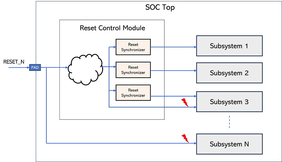
The reset at the System-on-Chip (SoC) top must not be connected, either directly or indirectly through combinational logic, to the input pins of the subsystems.
Each valid path must have a reset synchronizer on the path. We defined this check at both the top and block level.
Report: The graphic below illustrates how this connectivity error was identified and highlighted during the RTL level connectivity static sign-off process.
VII. Conclusion: Initial Deployment & Additional Insights
Our results clearly showed that our methodology to efficiently verify connectivity and glitch checks in the design using a static sign-off approach, significantly reduces analysis time, taking only minutes for block-level analysis compared to hours required by formal, simulation and TCL- based scripting methods for similar blocks.
Further, it delivered low noise reports through user-configurable options and pattern matching, while being adaptable to various design types, including design with complex control logic, clock gating, and power logic.
We also found additional advantages from using this static verification approach. First, we can now define connectivity checks for third party IP input/output, rather than sharing RTL code, improving our third-party IP sign-off process.
Second, during early design flow stages, in spite of not having a complete RTL, we were able to specify connectivity originating from the module with missing definitions. This allowed us to verify pin functionality and provide information to the physical design and verification team to address potential issues much earlier.