CDC Sign-Off for DFT Logic: Dream Chip Case Study
Presented by Herbert Blesse
Dream Chip
DAC 2022 presentation by Herbert Blesse of Dream Chip (edited transcript)
Case Study Overview
Herbert Blesse of Dream Chip. presents a case study on Dream Chip’s Clock Domain Crossing (CDC) Signoff Flow with DFT Logic using Real Intent Meridian CDC.
Importance of CDC Sign-Off for DFT Logic
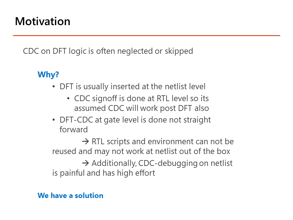
Clock Domain Crossing analysis is quite important – everyone does it on their RTL. From my personal experience, I’ve seen that CDC analysis of DFT logic is often neglected or skipped.
One reason for this is that DFT is usually not inserted until the netlist level. Earlier CDC sign-off during RTL does not always hold after inserting DFT logic.
Another potential cause for can be that DFT is not run in a straightforward manner. We often have circuitous scripts that cannot be reused out of the box. Additionally, CDC debugging on the netlist can be painful and take a lot of effort.
3 Key Factors for CDC Analysis of RTL with DFT Logic
There are three main factors that make life easier for Dream Chip and better support our CDC analysis and sign-off of DFT logic.
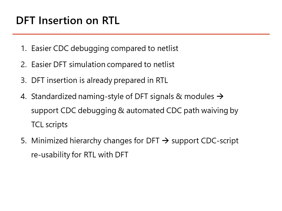
First, we do DFT insertion on the RTL. This results in easier debugging and easier simulation compared to doing it at the netlist level.
We also use a standardized naming style for DFT signals and modules, etc., which supports our clock domain crossing debugging and automated CDC path-waiving by Tcl scripts.
We also only make minimum hierarchy changes with our DFT logic.
Second, Dream Chip uses our internal SoC library of modules and cells. These library elements have integrated prepared DFT logic. The inputs of these DFT elements are tied and these DFT elements are connected in the DFT insertion.
We also implement CDCs utilizing SoC elements. This of course, makes the automated CDC path waiving and TCL scripts easy.
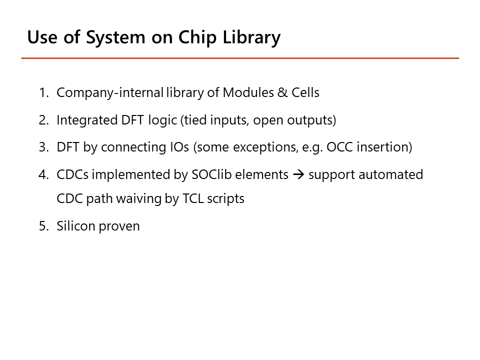
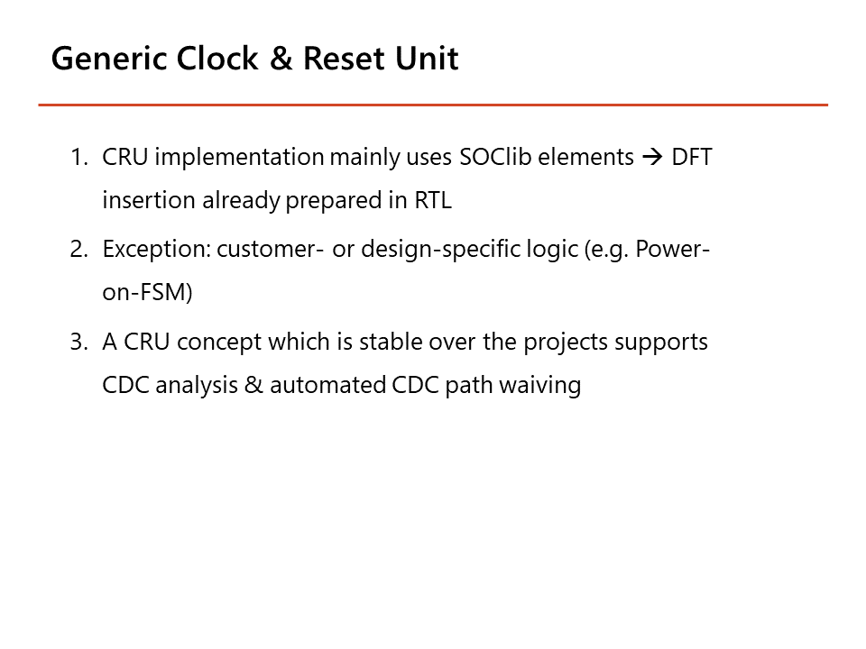
Third, we use a generic clock and reset unit approach.
This means that our CRU implementation uses mainly SoC elements – thus, the DFT insertion is already prepared in our RTL.
DFT Insertion Impact on Clock and Data Path
I will share three examples of how DFT logic can change or add new CDC paths.
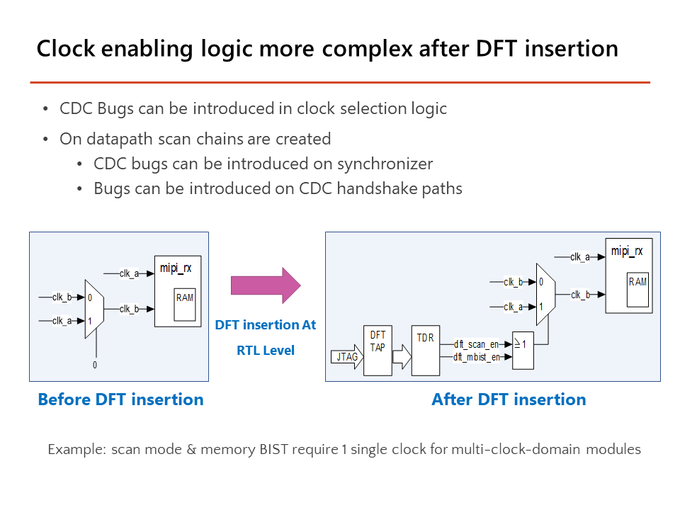
First, clock enabling logic becomes more complex after DFT insertion.
One example is an interface block containing a FIFO which uses a dual port RAM. We have two clocks — clock A and clock B. The DFT logic is already prepared and is tied to 0. After DFT insertion, we have additional DFT logic that controls this clock MUX.
In the end, for scan mode and for Memory BIST mode, we only need one clock here, which is done by this clock multiplexer. So, when it’s scan enabled or M-BIST enabled, we only have one clock.
The result is that the old CDC path is kept, and we get an additional path added by DFT.
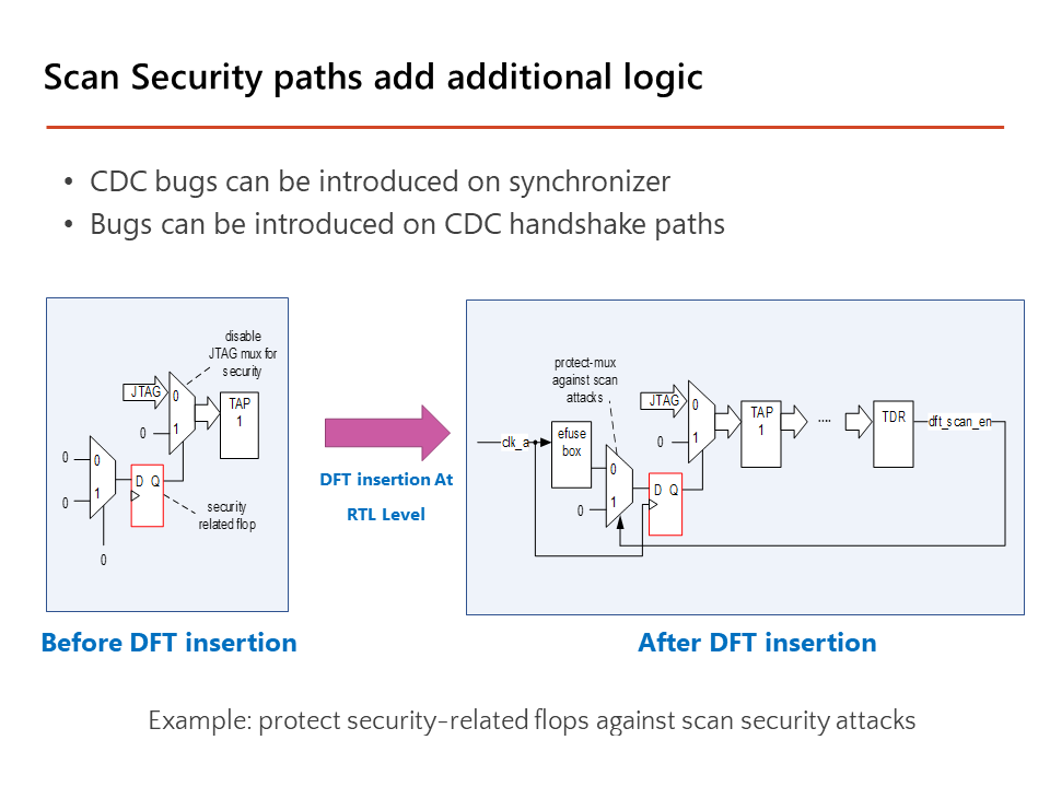
Second, scan security paths add additional logic. We have a simple and straightforward security example. We see the logic for disabling the JTAG; we have a JTAG interface and multiplexer that can disable this interface. The select of the multiplexer is driven by this flip-flop, which has prepared DFT logic on the D-input.
We can see that after DFT insertion, the select of the multiplexer is connected to the DFT logic and an eFuse box was added by DFT. We want to copy the content of eFuse box to this flop — that is the JTAG.
The copy process takes multiple clock cycles, so we have a multiplexer to make sure there is no scan attack done during these clock cycles. A hacker could try a scan attack to enable the scan mode and try to shift in a 0; this would disable the JTAG. But if we go to scan mode, only 1s can be shifted in that flop. In this way, we used DFT to close the security gap.
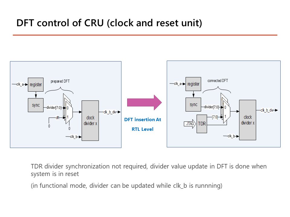
In our third example, we see the DFT control of the clock and reset unit. We have a configurable clock divider, which is set by the register. The register runs on a different clock domain than the clock divider, so we need synchronization for the normal functionality.
After DFT insertion, the DFT element is connected to a TDR so we can control whether we want to use the normal, functional configuration value or configure via a TDR.
There’s no synchronizer. While for normal functionality we want to change the divider on the fly with an ongoing clock, in DFT mode, we don’t need it.
So, in DFT mode, we first set the system on the right side to reset. Then we configure the divider and release the reset of the system — so the signals are stable, and we don’t need the synchronizer.
This is quite often done for DFT, so we don’t need to always have a synchronizer in DFT clock domain crossings. This is why analyzing the CDC path of the DFT logic is a bit more difficult than normal functionality CDCs, which usually have a synchronizer.
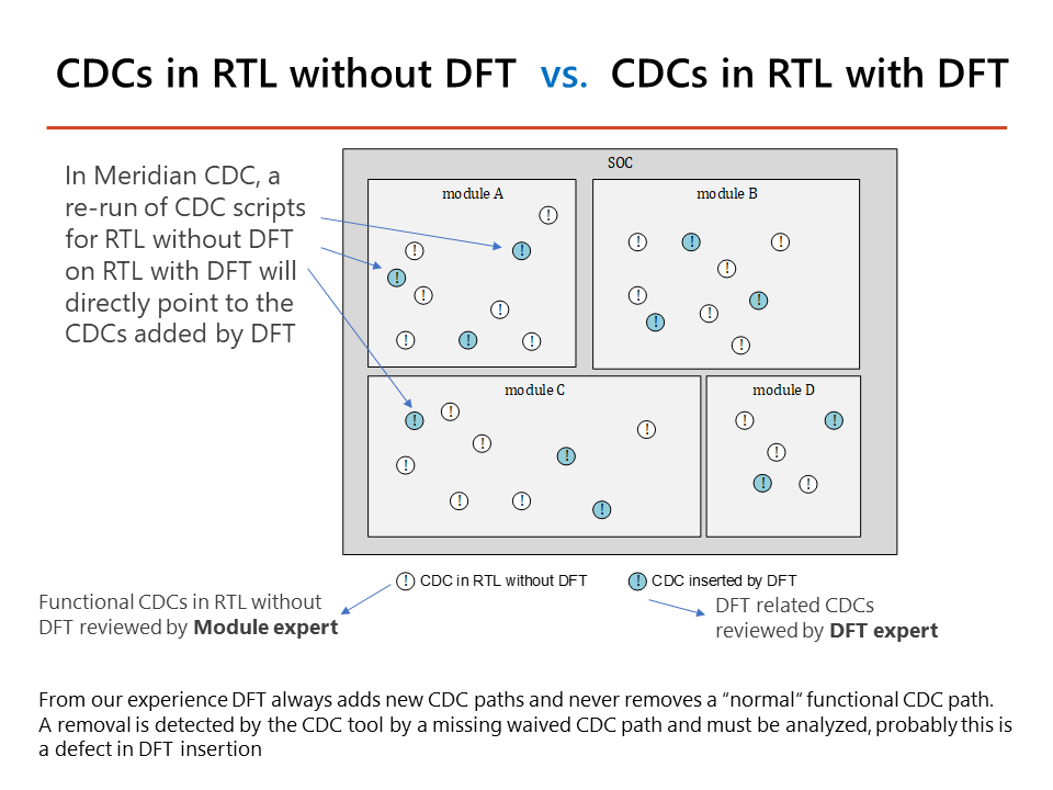
RTL Clock Domain Crossings with & without DFT
In this graphic, the white circles represent CDCs in RTL without DFT, and the blue circles stand for CDCs inserted by DFT.
And if we run CDC analysis on RTL without DFT as a first step, then all of the white circles are removed for the next run with RTL with DFT. Then we will only have the blue circles indicating CDCs with DFT logic.
We separate the two types so the white ones can be reviewed by a module expert, and the blue ones can be reviewed by a DFT expert. It makes sense to have this automatic separation, as usually these are two different people — the module expert does not want to be bothered with the DFT issues and the DFT expert does not want to be bothered with module issues.
An example result: If a white circle here was removed by an incorrect DFT insertion, then Meridian CDC will point us directed to the missing path. This indicates something went wrong and must be fixed, as from our experience, DFT generally only adds a CDC path, and never removes a CDC path for normal, functional logic.
Dream Chip’s Clock Domain Crossing Sign-Off Flow
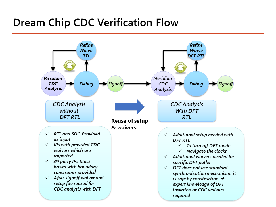
This slide shows our Dream Chip CDC verification flow. We start with [Real Intent’s] Meridian CDC, and then we get errors and warnings which we debug. If it is an issue or not wanted, we fix it in RTL. And then we run the tool and debug again for multiple iterations.
No errors and warnings should be left at the end. And then the module expert does the sign off, after reviewing all the waivers.
We then run a CDC analysis of our RTL with DFT logic. We restart the old scripts as a starting point — and then get errors and warnings which are only related to the DFT logic.
Then again, we debug and decide this is okay and can be waived, or is an error that needs to be fixed, and iterate until there are no remaining violations. Our DFT expert then reviews the waiver and completes the sign-off.
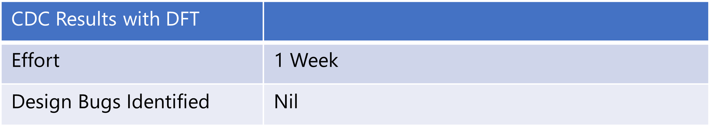
Dream Chip’s CDC Sign-Off Flow Results
We deployed our CDC sign-off flow with DFT logic on two designs.
Design one is the initial product SOC and designed two was a derivative.
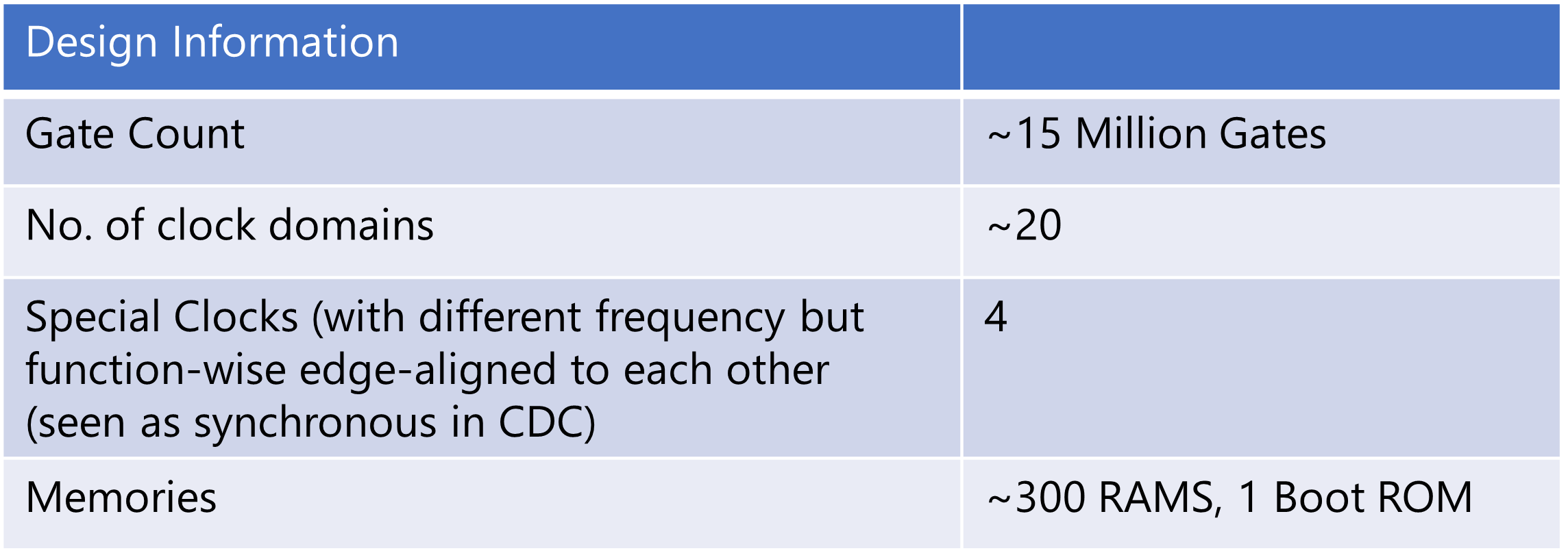
The gate count of our SOC chip was roughly fifty million gates. We had roughly twenty clocks coming out of the CRU — after synthesis, there were even more clocks.
And roughly 300 RAMs, with 1 boot RAM.
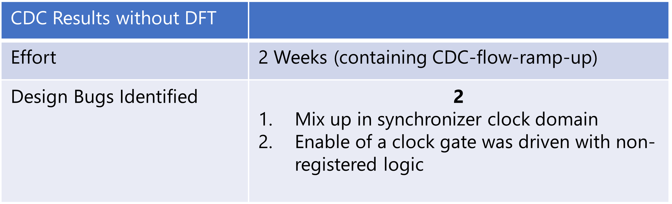
For the initial SOC, we needed two weeks, and the derivative only took two days. We found and fixed two CDC issues with Meridian CDC. One was a mix-up in the synchronizer clock domain. And the other one was a clock gate enable that was driven by non-registered logic.
As for CDC results logic with DFT — there we found one issue which was an CDC error in a DFT interface bridge. This was quite a tricky one.
In the end, we successfully completed our CDC analysis of DFT logic.