Architectural Compliance Checking Shift Left Using Static Sign-Off
SSO Symposium Presentation by Prakash Narain of Real Intent
Overview
Prakash Narain, president & CEO of Real Intent presented at Real Intent’s 2023 Static Sign-Off Symposium.
He covered shifting left with connectivity checking for architectural compliance, along with glitch checking. Below are lightly edited highlights of what he presented.
Structured Design Methodologies Manage Complexity
Semiconductor companies have been very creative in managing increasing chip and SoC complexities by using structured design methodologies. The architectures implement the functionality using a structured connection of functional components.
We can abstract the connectivity principles into a set of connectivity requirements. These connectivity or rules for any chip come from various sources like bus protocols, power management logic, debug logic, physical design constraints, memory connectivity, DFT connectivity, etc.
Shift left can be defined as the earliest possible efficient verification of a design step. So, if we think of connectivity — or design integration — as a design step, then how do we enable shift left there?
Connectivity checking is an efficient shift left verification of architectural compliance. This is the basis on which I will elaborate.

Connectivity Checking Shift Left in Action
Let’s go through architectural compliance and connectivity checking and sign-off shift left in action with a simple example using DFT.
Example of Shift Left in Action: DFT
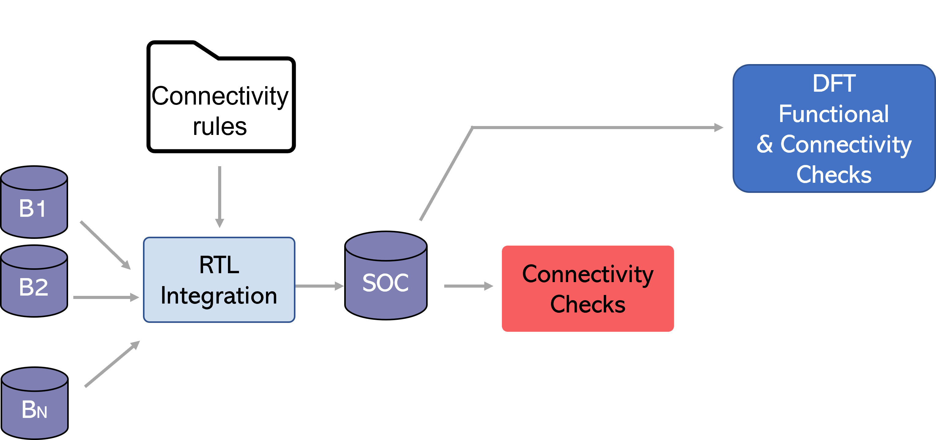
Let’s look at some DFT integration connectivity rules:
- Stitch a scan chain across boundaries using connectivity rules, so there are multiple port-to-port connections.
- Connect the scan compression and decompression logic on-chip clock controllers to blocks.
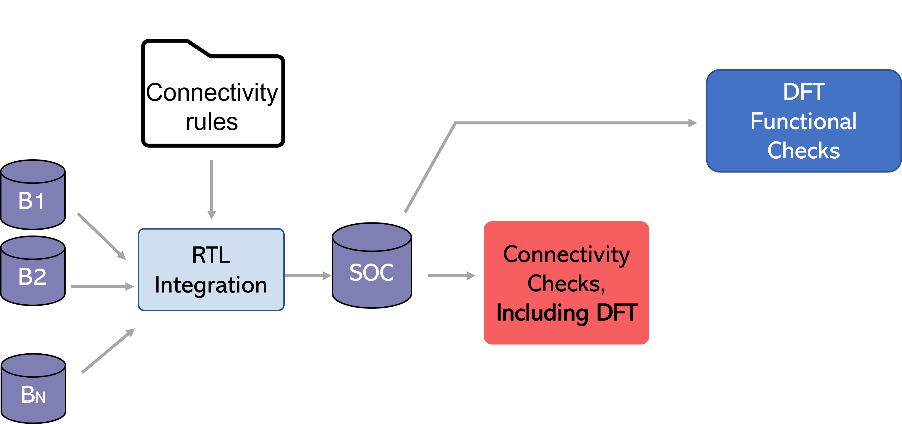
Designers have the option to verify these rules early in their RTL as part of connectivity checking, or they can wait to verify them during functional DFT checking
Connectivity rules have higher granularity
Notice that the connectivity rules have a higher level of granularity. For example, if the port-to-port connection went wrong in the scan chain and is broken in four places.
- A DFT functional checker would likely provide only two breakage points — one at the start and one at the end. It would not identify the breakage points in the middle during the first iteration.
- DFT connectivity rule checker can have checks for each point-to-point connection, and all the ones that are broken will get reported.
This granularity of checking and non-overlapping checks enables a better experience for static sign-off; engineers will achieve faster root cause detection with connectivity related failures specifically to DFT.
Expanding connectivity checking shift left to other functions
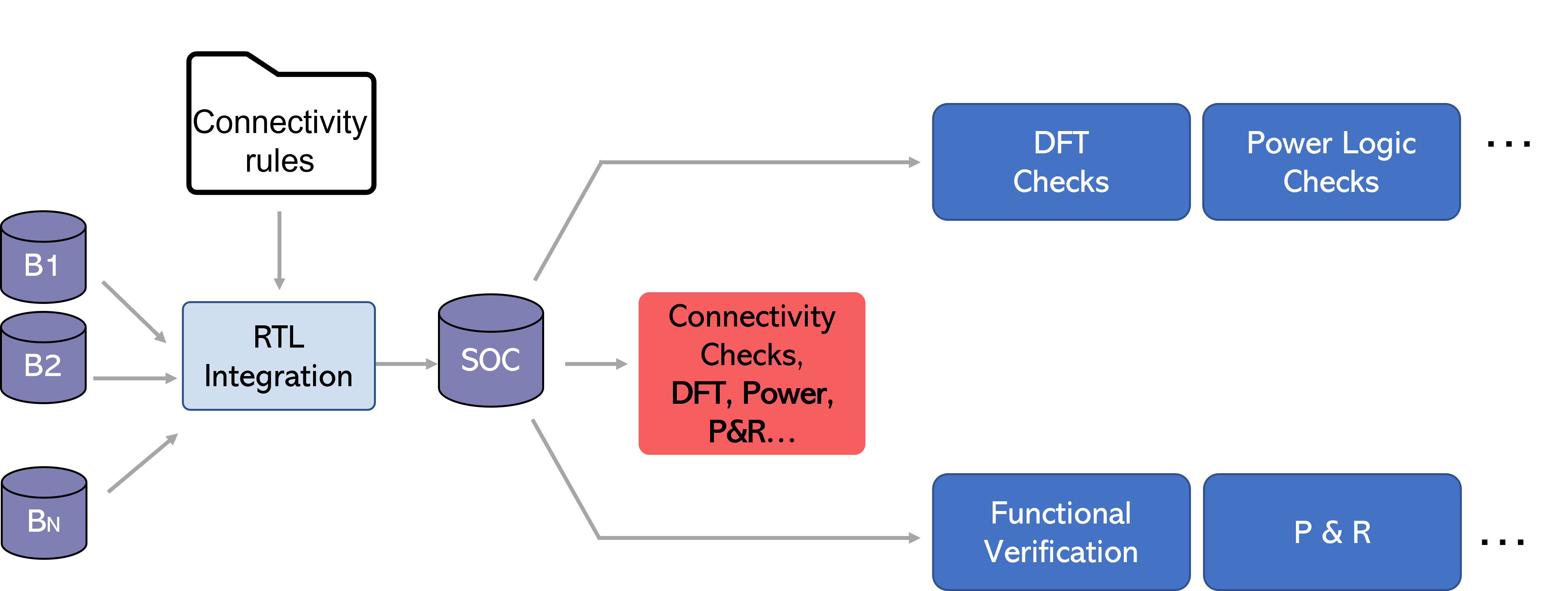
We can expand this connectivity shift left concept beyond DFT.
Connectivity rules come from various sources; thus, as soon as engineers complete a design step, they can check the connectivity of all these requirements or architectural compliance requirements in one system, and right away get the feedback from it.
Glitches Fail Chips
Next, let’s discuss glitches. A glitch is a transition that is shorter than the clock period; if it gets captured at the clock edge, there is a problem.
Typically, asynchronous interactions within the designs are vulnerable to glitches in the netlist.
- This means these are static timing analysis exceptions and will not be caught by static timing analysis.
- Functional simulation tends to be zero delay — so they will not be caught by functional simulation.
We can design a cost-effective verification methodology by combining structural connectivity principles with netlist glitch checking.
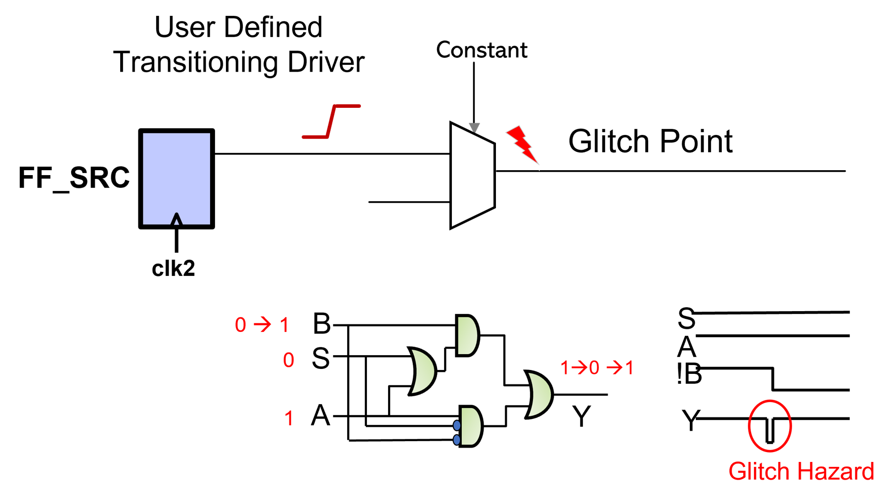
Structured Glitch Checking Methodology
Clock Domain Crossings
We know there can be glitch failures with clock domain crossings (CDC). This is because with CDC, we can think of the data path crossing as a functional multicycle path — we don’t want the data to be captured on the next edge.
CDC is encapsulated within interfaces, and usage of pre-verified components for CDC interfaces is a standard practice.
So, structural glitch avoidance principles can be included within the CDC components.
Timing exceptions & power management logic
For domains such as timing exceptions and power management logic, path structuring may be necessary, with synthesis tool restrictions during path optimization. For example, inserting a “do not touch component” to partition the paths, where the designer does not want the path to be structured across a component in the middle of a path.
The engineer can then verify that presence of those components in the connectivity in the RTL and verify that the connectivity is maintained in the netlist. The designer can also run glitch checking at the netlist level.
SafeConnect: RTL & Netlist Connectivity & Glitch Sign-Off
Real Intent has a product called SafeConnect for RTL and netlist connectivity and glitch signoff.
SafeConnect reads in RTL, constraints, and UPF, along with the user defined rules that may be created locally or instantiated from a dictionary. After the analysis, the tool produces the connectivity reports; designers can iterate in this cycle.
Once the RTL is signed off, designer can go through synthesis and other processes, and the same checking can be run at the netlist level. The goal is to implement this checking after each design step, to achieve an efficient shift left.
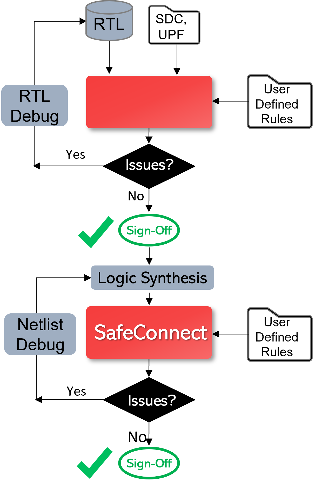
Ultimately, shifting verification to the left with static sign-off will be successful based upon a superior designer experience — including fast tool performance, setup and debug efficiency, and complete and expanding coverage. Below are the ways that Real Intent ensures SafeConnect provides this for connectivity and glitch sign-off.
1. Quick & Efficient Rules Definition
Engineers can quickly and conveniently define specific rules for their company, utilizing Real Intent’s existing library of checks as needed.
Let’s look at an example of check that an engineer might define: “At the full chip level, ensure there is no improper connectivity of resets relevant for retention logic connecting to flops that are non-retention flops.”
To specify such a rule, the engineer would first create a source group and a destination group of objects, and then specify that there cannot be a connection between these groups.
In this case, just three commands can define a check at block or full chip level to avoid improper connectivity from specific signals to undesired flip flops. There are more variations that allow a more fine-grained specification.
- Create source group – options to select modules/instances/signals can be used
- Create destination group – option to select FFs in full chip / specific modules / instances
- Specify command to check that no connection exists between signals in source group to destination group
2. Dictionary for Full Coverage
To elaborate on Real Intent’s library of checks, for example there are templates available for retention resets and clocks checking, extra margin adjustment memory connectivity, glitch occurrence and propagation, DFT-related templates, debug buses and abutment and partial abundant for some physical design constraints.
3. Diverse Connectivity Principles
Rule diversity is important. For example, between buses you can have cross-connections; engineers may wish to only allow certain connections, or no connections between groups. They may wish to exclude specific source and destinations from larger groups, etc.
SafeConnect has various mechanisms that are available for customizing and creating very fine-grained rules for the nature of connectivity desired. Once the policy is created then designers can create a policy out of the dictionary and instantiate appropriate checks in their designs. Further, engineers can write checks to further improve the granularity for local checks.
4. High Capacity & Performance
SafeConnect static sign-off is dramatically faster for connectivity and glitch checking than the alternatives — which are formal verification or making use of TCL interfaces to write tracers, etc.
Those methods have lower capacity and run relatively slow — in addition to having an inconvenient setup.
SafeConnect has been designed for this particular application; Real Intent developed customized technology for it to provide the highest possible capacity and performance.
5. Customized Connectivity Debug
We have a customized application within iDebug for connectivity issue debug.
6. Example Connectivity & Glitch Checks
Example Connectivity Check Report
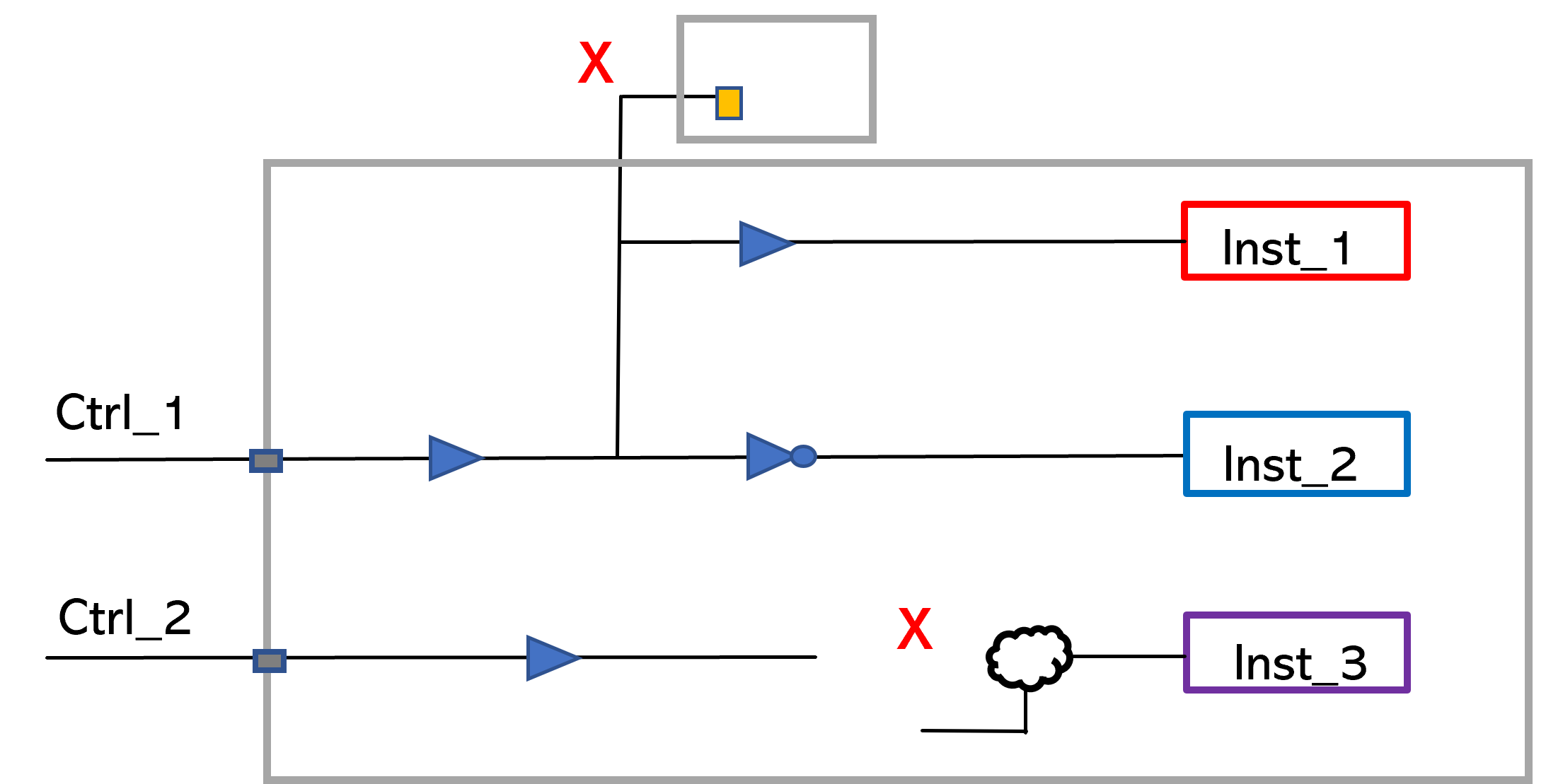
A simple example for a connectivity report might be that a control signal is expected to drive only the enable pins of specific instances without any combinational logic on the path. This check can be easily specified, and the broken connections or extra fanout failures are reported. There’s an extra connection that will be reported here and there is a broken connection whether it was connected through logic or it’s not connected at all.
Example Glitch Checking Report
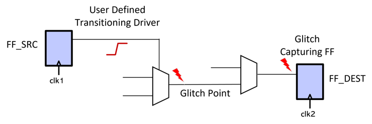
The glitch report will verify that a source to a destination path is glitchy. The glitch check can be very easily specified with the source to destination path through points.
The glitch source path, the glitch point, and the capturing flop are the elements that would be reported along the paths.
Methodology: Left Shift of Architectural Compliance
The starting point methodology is for the CAD group to create a dictionary of standard rules and this is the attempt that we have made is that the creation cost is minimal. Then users instantiate and activate relevant rules based upon what they’re looking to accomplish.
This methodology can be integrated into a continuous integration process to enable left shift because of very fast run time and high debug efficiency.


